
É um sistema de símbolos, regras e definições usadas para definir a geometria das peças mecânicas. GD&T é uma das ferramentas mais poderosas disponíveis que podem melhorar a qualidade, reduzir custos e encurtar o tempo de entrega. O GD&T no desenho deve, antes de mais nada, capturar a intenção do projeto. No entanto, o melhor design do mundo não vale nada se não puder ser produzido. Por isso é necessário que a produção/fornecedores e a qualidade estejam envolvidos com os requisitos que são colocados no desenho. Quando não estão envolvidos, os desenhos geralmente têm tolerâncias excessivamente rígidas e resultam em peças não produzíveis. Pelo menos não produzíveis no nível de qualidade, custo e pontualidade esperados pela indústria.
It is a system of symbols, rules and definitions used to define the geometry of mechanical parts. GD&T is one of the most powerful tools available that can improve quality, reduce cost and shorten delivery time. All of this is possible when the concurrent engineering team is involved with the creation of the drawing. GD&T on the drawing must first and foremost capture design intent. However, the best design in the world is worthless if it cannot be produced. That is why it is necessary for production/vendors and quality to be involved with the requirements that are placed on the drawing. When they are not involved, the drawings often have overly tight tolerances and result in non-producible parts. At least not producible at the quality level, cost and timeliness expected by industry.
Não há outra forma padronizada de controlar a geometria das peças. Os métodos antigos nunca foram padronizados. Muitas pessoas achavam que sabiam o que significava o antigo método. O problema era que muitas pessoas interpretavam o desenho de forma diferente. GD&T é padronizado e matematizado o que significa que quem conhece a norma, sabe o que significa o desenho. Quem cria, aprova ou usa o desenho deve saber ler o desenho. No mundo de hoje, se você não conhece GD&T, você não sabe ler!
There is no other standardized way to control the geometry of parts. The old methods were never standardized. Many people thought they knew what the old method meant. The problem was that many people interpreted the drawing differently. GD&T is standardized and mathematized which means that anyone who knows the Standard, knows what the drawing means. GD&T is today’s Print Reading. Anyone who creates, approves or uses the drawing should know how to read the drawing. In today’s world, if you do not know GD&T, you do not know how to read!
A garantia da qualidade no desenvolvimento de um produto depende de uma correta especificação que impacta direta ou indiretamente em custo e prazo.
Existem diversas formas para se detalhar um projeto de forma a organizá-lo. Consideramos 4 etapas no desenvolvimento de um produto como proposta para demonstração dos prazos e custos:
• Conceitual: definição dos conceitos do produto junto ao cliente
• Representativa: definição do design do produto
• Industrialização: definição e construção dos equipamentos, linha de montagem, ferramentais, dispositivos de controle etc.
• Produção
Quality assurance in product development depends on a correct specification that impacts directly or indirectly in cost and time.
There are several ways to detail a project in order to organize it. We consider 4 stages in product development as a proposal to show deadlines and costs:
• Conceptual: definition of product concepts with customer
• Representative: product design definition
• Industrialization: definition and construction of equipment, assembly line, tools, control devices etc.
• Production
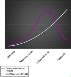
Os custos do desenvolvimento de produto podem ser expressos como demonstrado na curva acima. Os custos são mais representativos na etapa de industrialização. Por isso, a etapa denominada representativa é a última oportunidade de não incorrer em custos elevados para o desenvolvimento do projeto.
Product development cost can be expressed as shown in curve above. Cost are more representative in the industrialization stage. For this reason, the so called representative stage is the last opportunity not to incur high costs for the product development.
Produtos tem suas variações normais de produção que influenciam na qualidade do mesmo. Para se ter um produto com qualidade reconhecida no mercado é necessário um projeto robusto.
Definimos aqui que projeto robusto é aquele que não é sensível às variações da produção, ou seja, as variações inerentes do processo produtivo não compromete a qualidade do produto.
Para isto, podemos utilizar muitas metodologias durante o desenvolvimento que minimiza a possibilidade de falhas durante o projeto ou da vida do produto.
A análise funcional e o FMEA são algumas dessas metodologias que podemos utilizar para reduzir os riscos e desenvolver um projeto robusto.
Products have their normal production variations that influence their quality. In order to have a product with recognized quality in the market, a robust design is necessary. We define here that a robust design is one that is not sensitive to variations in production, that is, variations inherent in the production process do not compromise the quality of the product.
For this, we can apply many methodologies during development that minimize the possibility of failures during the project or the life of the product.
Functional analysis and FMEA are some of these methodologies that we can use to reduce risks and develop a robust design.
The concept of the parts being interchangeable brings the expectation of them assembling the first time and obtaining the expected performance defined by their function. Parts can be produced in different processes, different plants and even in different countries and still fulfill their function and allow assembly without rework.
All processes have their qualitative variation that influence their assemblability and function. To fulfill part function and assemblability, customer must clearly define part in a language recognized by the supplier. In addition, both customer and supplier must clearly understand the means of measurement to ensure that what has been produced is what was defined.
Sistema cartesiano
Até a época de Leonardo da Vinci (1452-1519) os desenhos mecânicos eram mais artísticos que técnicos. Mostravam algumas dimensões a título ilustrativo. A grande evolução ocorreu em 1638, quando René Descartes criou a geometria analítica, que passou a ser utilizada para expressar os requisitos dimensionais dos projetos mecânicos. Sem descartar Descartes, deve-se mencionar que, por mérito, o sistema cartesiano deveria denominar-se sistema fermatiano, porque foi Pierre de Fermat (1601-1655) quem descobriu as equações da linha reta e da circunferência, e as equações mais simples da elipse, da parábola e da hipérbole.
Sistema geométrico
Na década de 50, o sistema cartesiano foi aperfeiçoado por Stanley Parker, que descobriu o campo de tolerância circular, e ganhou o nome de Geometric Dimensioning & Tolerancing – GD&T.
O GD&T possui recursos de linguagem para comunicar as tolerâncias geométricas e dimensionais, recursos matemáticos para defini-las, e recursos estatísticos e computacionais para calcular o índice de capacidade dos processos, Cp.
GD&T significa Dimensionamento e Tolerância Geométrica. É um sistema de símbolos, regras e definições usadas para definir a geometria das peças mecânicas.
GD&T é uma das ferramentas mais poderosas disponíveis que podem melhorar a qualidade, reduzir custos e reduzir o tempo de entrega. O GD&T no desenho deve, em primeiro lugar, capturar a intenção do projeto. No entanto, o melhor design do mundo é inútil se não puder ser produzido.
Em resumo, GD&T são:
Não há outra maneira padronizada de controlar a geometria das peças. Os métodos antigos são ambíguos. O problema é que muitas pessoas interpretam o desenho de maneira diferente. O GD&T é padronizado e matematizado, o que significa que qualquer um que conheça a norma sabe o que o desenho significa.
Cartesian System
Until Leonardo da Vinci (1452-1519) mechanical drawings were more artistic than technical. They showed some dimensions for illustrative purposes. The great evolution occurred in 1638, when René Descartes created the analytical geometry, which started to be used to express the dimensional requirements of mechanical designs. Without discarding Descartes, it should be mentioned that, by merit, the Cartesian system should be called the Fermatian system, because it was Pierre de Fermat (1601-1655) who discovered the equations of the straight line and the circumference, and the simplest equations of ellipse, parabola and hyperbola.
Geometric System
In the 1950s (some literature mentions the 1940s), the Cartesian system was perfected by Stanley Parker, who discovered the circular tolerance field, and called Geometric Dimensioning & Tolerancing – GD&T. GD&T is a language resources to communicate geometric and dimensional tolerances, mathematical resources to define them, and statistical and computational resources to calculate the process capacity index, Cp.
GD&T means Geometric Dimensioning and Tolerancing. It is a system of symbols, rules and definitions used to define the geometry of mechanical parts.
GD&T is one of the most powerful tools available that can improve quality, reduce costs and reduce delivery. GD&T on drawing must, first of all, capture the intention of the design. However, the best design in the world is useless if it cannot be produced.
In summary, GD&T are:
There is no other standardized way to control the geometry of parts. The old methods are ambiguous. The problem is that many people interpret the design differently. GD&T is standardized and mathematicised, which means that anyone who knows the standard knows what the design means.
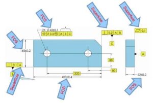
Basicamente existem dois tipos de elementos: elementos de tamanho (FOS) e superfícies. Elementos de tamanho são aqueles que tem limites de tamanho, podem conter ou ser contido por um envelope de acoplamento e ter pontos opostos.
A interpretação dos controles depende do tipo de elemento. Da mesma forma a compreensão dos datums e como se estabelece depende do seu tipo.
As tolerâncias geométricas devem ser especificadas conforme os requisitos funcionais da peça. Uma peça é definida por elementos que podem ser um ponto, uma linha ou uma superfície. Estas superfícies podem ser elementos integrais ou elementos derivados.
Basically there are two types of features: feature of size (FOS) and surfaces. feature of size are those that have size limits, can contain or be contained by a mating envelope, and have opposite points.
The interpretation of controls depends on the type of feature. Likewise, understanding datums and how they are established depends on their type.
Geometric tolerances must be specified according to the functional requirements of the part. A part is defined by features that can be a point, a line or a surface. These surfaces can be integral elements or derived elements.
A compreensão da hierarquia do GD&T simplifica muito na compreensão e aplicação dos controles geométricos em uma peça mecânica.
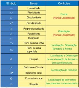
Existem 14 tipos de tolerâncias (sistema ISO/GPS) ou 12 tipos (ASME Y14.5) que podemos utilizar nos desenhos mecânicos. Estes controles são divididos em 3 grupos:
➢ Forma: retitude (linearidade), planeza (planicidade), circularidade e cilindricidade;
➢ Orientação: perpendicularidade, paralelismo e inclinação
➢ Localização: perfil de linha, perfil de superfície, posição, batimento circular, batimento total, concentricidade e simetria.
Para controles de superfícies (elementos integrais) podemos localizar os elementos utilizando perfil de linha, perfil de superfície, posição (superfície plana – somente na ISO), batimento circular (superfície cilíndrica) e batimento total (superfície cilíndrica). De forma geral estes controles já definem a orientação e a forma. Assim, a aplicação dos controles de orientação e forma só serão necessários para refinamento dos controles de localização.
Para controle de ponto central, plano central ou eixo (elementos extraídos/derivados) podemos localizar os elementos utilizando posição, concentricidade e simetria (na ASME Y14.5 não é mais permitido a concentricidade e a simetria). De forma geral estes controles já definem a orientação. Assim, a aplicação dos controles de orientação só serão necessários para refinamento dos controles de localização. Como no sistema ISO/GPS o princípio da independência é o padrão, podemos também definir controles de forma para elementos de tamanho ou utilizar o modificador de envelope. Se aplicarmos a ASME Y14.5 precisamos seguir a regra #1 que estabelece que o tamanho controla a forma. Assim, na ASME Y14.5, podemos colocar um controle de forma se for necessário um refinamento.
Understanding the GD&T hierarchy greatly simplifies understanding and applying geometric controls to a mechanical part.
There are 14 types of tolerances (ISO/GPS system) or 12 types (ASME Y14.5) that we can use in mechanical drawings. These controls are divided into 3 groups:
➢ Form: straightness, flatness, circularity and cylindricity;
➢ Orientation: perpendicularity, parallelism and angularity
➢ Location: line profile, surface profile, position, circular runout, total runout, concentricity and symmetry.
For surface controls (integral elements) we can locate features using line profile, surface profile, position (flat surface – ISO only), circular runout (cylindrical surface) and total runout (cylindrical surface). In general, these controls already define the orientation and form. Therefore, the application of orientation and shape controls will only be necessary to refine the location controls.
To control the central point, central plane or axis (extracted/derived features) we can locate features using position, concentricity and symmetry (in ASME Y14.5 concentricity and symmetry are no longer allowed). In general, these controls already define the orientation. Thus, the application of orientation controls will only be necessary to refine the location controls. As in the ISO/GPS system the principle of independence is the default, we can also define form controls for feature of size or use the envelope modifier. If we apply ASME Y14.5 we need to follow rule #1 which states that size controls form. So at ASME Y14.5, we can put in a form control if refinement is needed.
Estamos entusiasmados por ter a oportunidade de ajudá-lo a ter sucesso em sua aventura de aprendizado em GD&T. É uma chance para você e sua empresa se destacarem em sua participação de mercado e carreira.
We are excited to have the opportunity to help you succeed in your GD&T learning adventure. It’s a chance for you and your company to rise above the pack in your market share and career.
Nunca houve um momento melhor ou mais importante para aprender e empregar GD&T. A 2i Inteligência Industrial se dedica a fornecer a você o melhor treinamento de GD&T disponível. Entre em contato conosco para obter mais informações usando este formulário de contato ou ligando para (31) 99992 9979.
There has never been a better or more important time to learn and employ GD&T. 2i Inteligência Industrial is dedicated to providing you the best GD&T training available. Please contact us for more information by using this contact form, or by calling us at +55 (31) 99992 9979.716-785-6015.
Temos profissionais especializados em GD&T e representamos a Tec-Ease (www.tec-ease.com) no Brasil
Copyright © 2022 All rights reserved